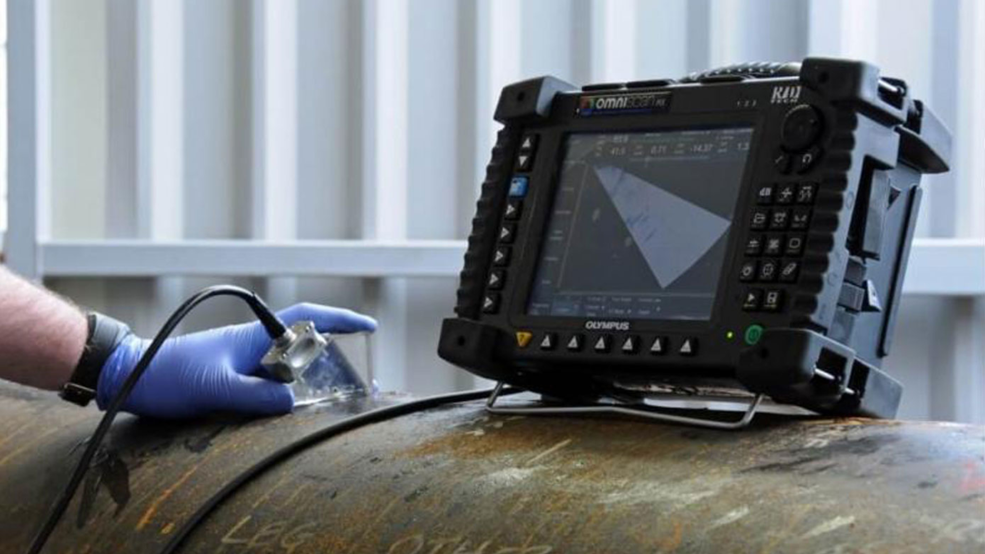
Time of Flight Diffraction (TOFD).
Time of Flight Diffraction uses two ultrasonic transducers in a pitch-catch meth-od to introduce ultrasonic sound waves into the test piece for inspection. The transducers produce three distinct waves with different characteristics, paths and velocities. The sensitivity of the Ultrasonics involved in TOFD make this in-spection much easier to evaluate and size defects for length and depth.
TOFD is generally used on piping and vessel welds. It is a useful tool in finding defects from equipment production, as well as ser-vice-induced defects. Weld washout due to process, cracking in coke drum welds; gen-eral existing or new weld production defects as well as surface corrosion can be detected and measured using the TOFD technique. Since there is no need to raster the trans-ducers, TOFD is preformed in a single parallel line scans which makes data col-lection fast. Up to 250 linear feet of weld can be inspected a day using this tech-nique and equipment.
Phased Array ultrasonic Testing.
PA provides sharper detection capability for off-angle cracks, and is capable of displaying multiple presentations simultaneously. PA applies computer-controlled excitation to individual elements in a multi-element probe. By vary-ing the timing of the excitation, the sound beam can be swept through a range of angles. The shape of the beam may also be modified to a specific focal dis-tance or spot.
Applications:
1.Ultrasonic Detection of Wet Hydrogen Damage
2.Ultrasonic Detection of Thermal Fatigue (Creep) Damage
3.HIC/SOHIC detection and analysis (Hydrogen Induced Cracking and Stepwise Orientated Hydrogen Induced Cracking)
4.HTHA (High Temperature Hydrogen Attack)
5.Wet H2S Cracking Detection
Long Range Ultrasonics (LRGUT).
The Long Range Guided Wave Ultrasonic Technique (LRGUT) or as it is sometimes called, Long Range Ultrasonic Tech-nique (LRUT) is a screening tool to inspect 100% of a pipe segment from one single location and detect corrosion and loss of integrity in pipelines.
The device induces torsional or longitudinal guided waves into the pipe body and propagates the wave along the pipe segment being inspected. When the guided waves identify an anomaly or pipe feature, the waves convert into
laminar waves and reflect back to the LRGUT Tool’s original location. We use a laptop computer to digitally capture the results. The time-of-flight for each signature is calculated to determine the distance from the tool. The cross sectional area is calculated by amplitude and then the circumferential extent determined by the focused beams (broken down in octants) to determine the significance of the defect.
Short Range Ultrasonics (SRGUT).
The Short Range Guided Wave Ultrasonic Technique (SRGUT) is a screening tool designed to test the annular plate of above ground storage tanks (AST’s) while the tank remains in-service. The technique is based on the concept of pulsing guided laminar waves into the base material from the chime area. The waves propagate up to three feet into the annular plate. When corrosion, pitting, erosion are present the ultrasonic waves mode convert and are received by the same transducer. The technique is also being used to test for corrosion under pipe supports, corrosion at soil air interfaces, and similar difficult to access locations.
Figure one depicts the transducer placement on the chime plate propagating long range ultrasonic waves into the annular plate. The sound reflects at top side or underside corrosion providing a c-scan image of the defect. The signal strength at the defect provides evidence of the depth and overall morphology of the defects
Figure two provides a visual presentation of the collected data providing distance inspected, with of inspection along with details on the indications identified. Some limitations exist when using this technique to including: Top or Bottom Side Differentiation Must Have 2” Space for Probe Placement.
SRGUT has become a proven and reliable technique as one method for determining the integrity of tank annular plates where the highest probability of corrosion exists to help prioritize out of service tank maintenance requirements.
Magnetic Flux Leakage (MFL)
- Inspection technique suitable for wall-loss detection and measurement of sharp
defects, such as pitting, grooving, and circumferential cracks.
- Applicable to ferromagnetic tubing
- Effective for testing aluminum-finned carbon steel tubes because the magnetic
field is mostly unaffected by the fins.
- A good Back-up inspection to Remote Field Testing.
Tubular Services.
IRIS (Internal Rotating Inspection System)
IRIS is an ultrasonic technique used for the inspection of a wide range of materials, including both non-ferromagnetic and ferromagnetic tubing.
- Allows for the detection and sizing of wall loss as a result of corrosion, erosion,
tube-to-tube wear, pitting, fretting, cracking and baffle cuts.
- Focused ultrasonic probe and a rotating mirror to produce a helical scan.
- Ultrasound is reflected from the tube ID and OD and the time difference is used
to calculate the thickness.
- IRIS is a great backup and verification tool for the other tube inspection techniques
- IRIS data to be presented as a B, C, or D-scan image.
Remote Field Testing (RFT)
- Full wall inspection of ferromagnetic tubes
- Used for the detection and sizing of wall thinning caused by corrosion, erosion,
wear, pitting and baffle cuts.
- Used to inspect boilers, feed water heaters, air coolers, and carbon steel heat
Exchangers.
Eddy Current Testing (ECT)
- Eddy Current is a cost effective and reliable way to inspect tubing.
- Inspect non-ferromagnetic tube and materials.
- Condensers, feed water heaters, air conditioners, chillers, and other heat exchangers
- Detection and sizing of metal discontinuities such as corrosion, erosion, tube-to-tube
ear, pitting, fretting, cracks, etc.
- Multi-frequency inspection with mixing and filtering capabilities.
- Data is recorded and archived which will allow you to track the corrosion rate for
each tube.

